Lunar Driving Simulator History
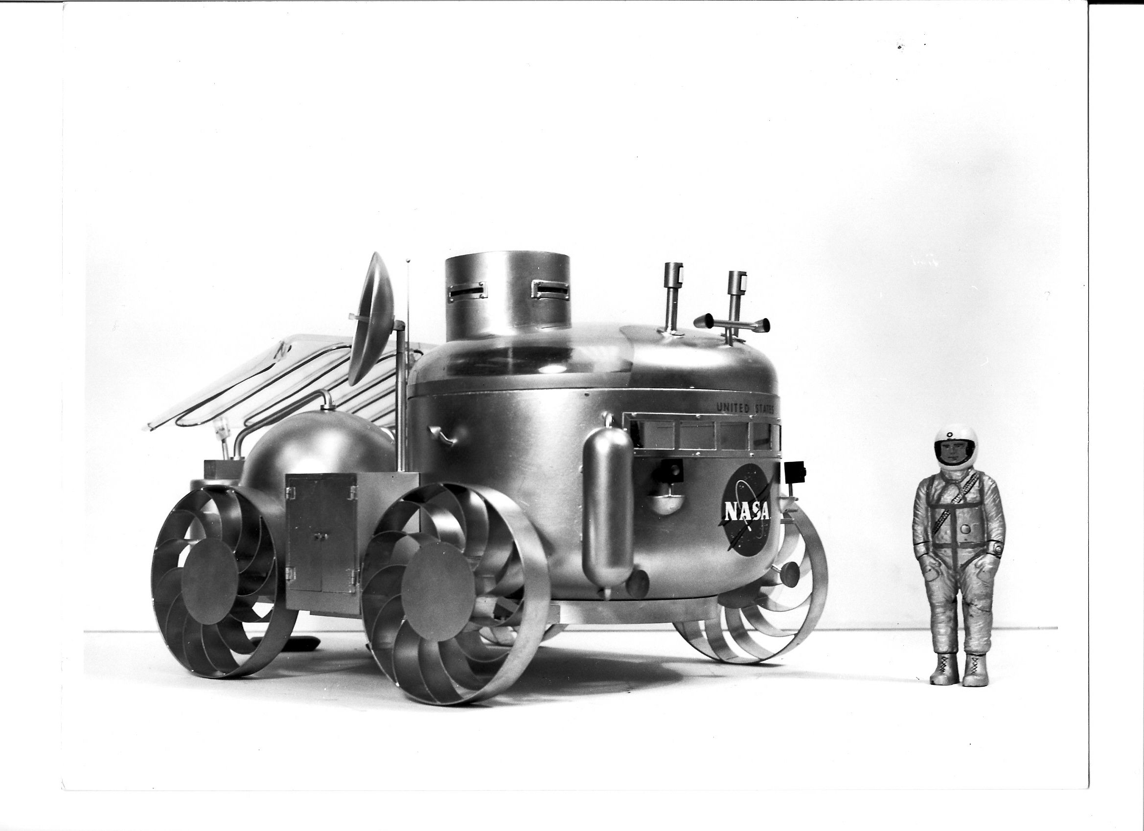
Early NASA MSFC/Northrop MOLAB Concept.
This vehicle concept evolved from the study contract NAS8-11096 in support of the early Apollo Logistic Support System studies that were being consider around 1963 to early 1964. This vehicle mock up concept was constructed at MSFC and was used later to study the human factors aspect of conduction lunar explorartion missions.This concept was to be flown to the Moon using a separate Saturn V vehicle and landed automatically there.
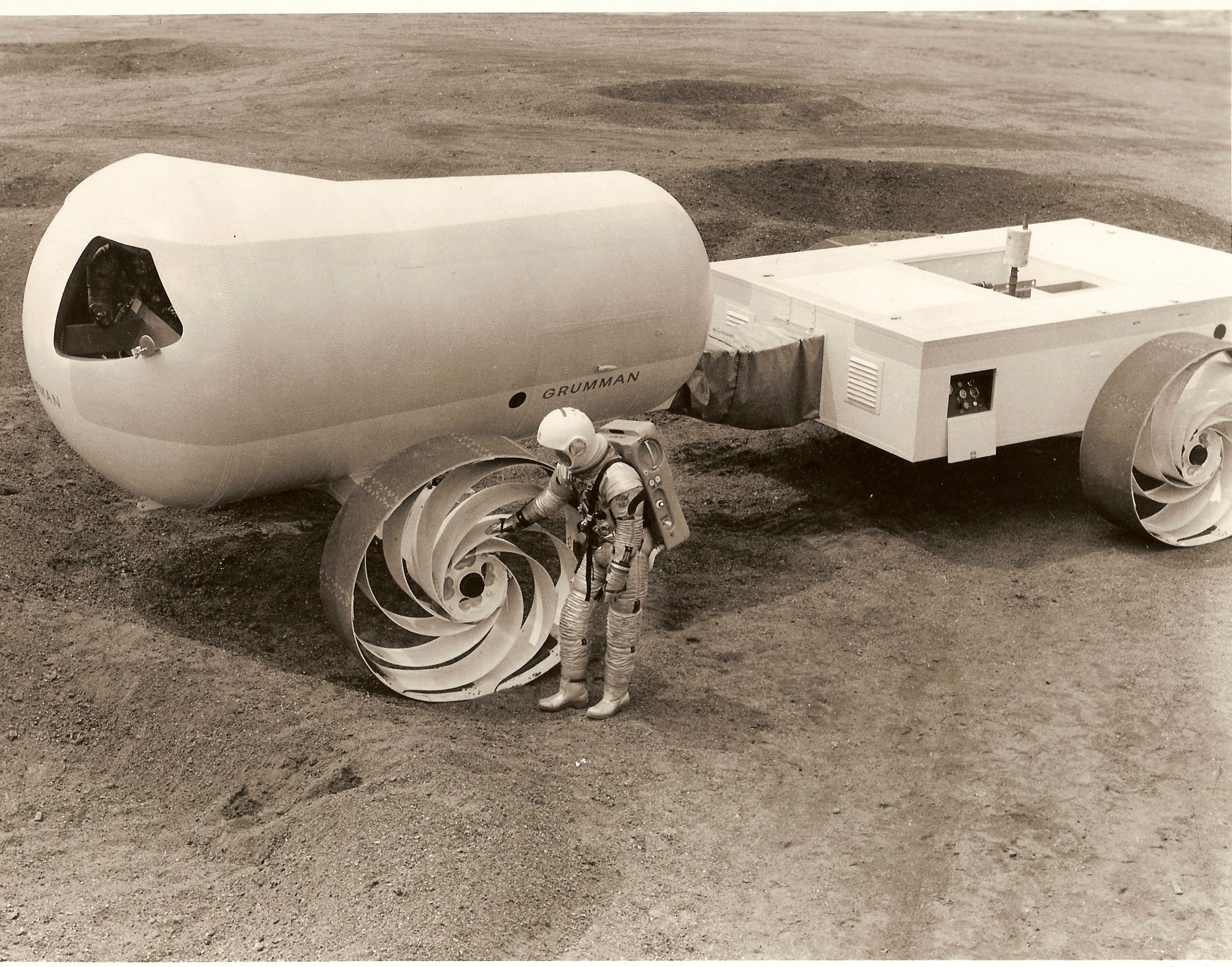
Early Grumman Concept for a MOLAB.
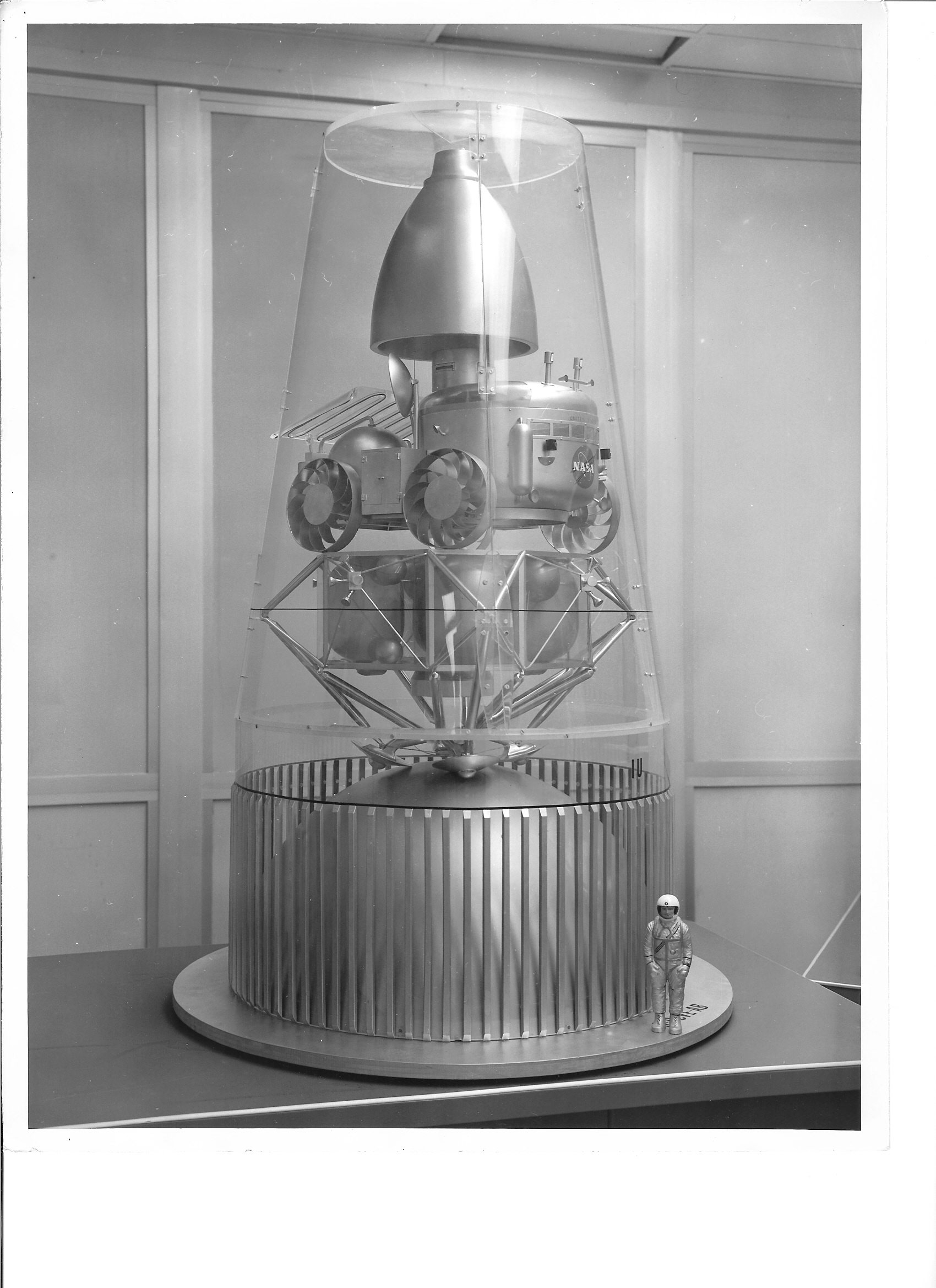
MOLAB Vehicle as stowed for transport to the Moon by the Saturn V.
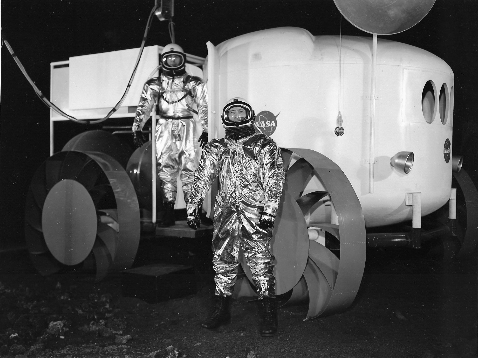
This is a photo of Mike Vacarro(NASA MSFC) and Hayden Grubbs (Brown Engineering) siuted up and preparing to do a human factor exercise and behind them is the NASA Marshall Space Flight Center MOBLAB Simulator.
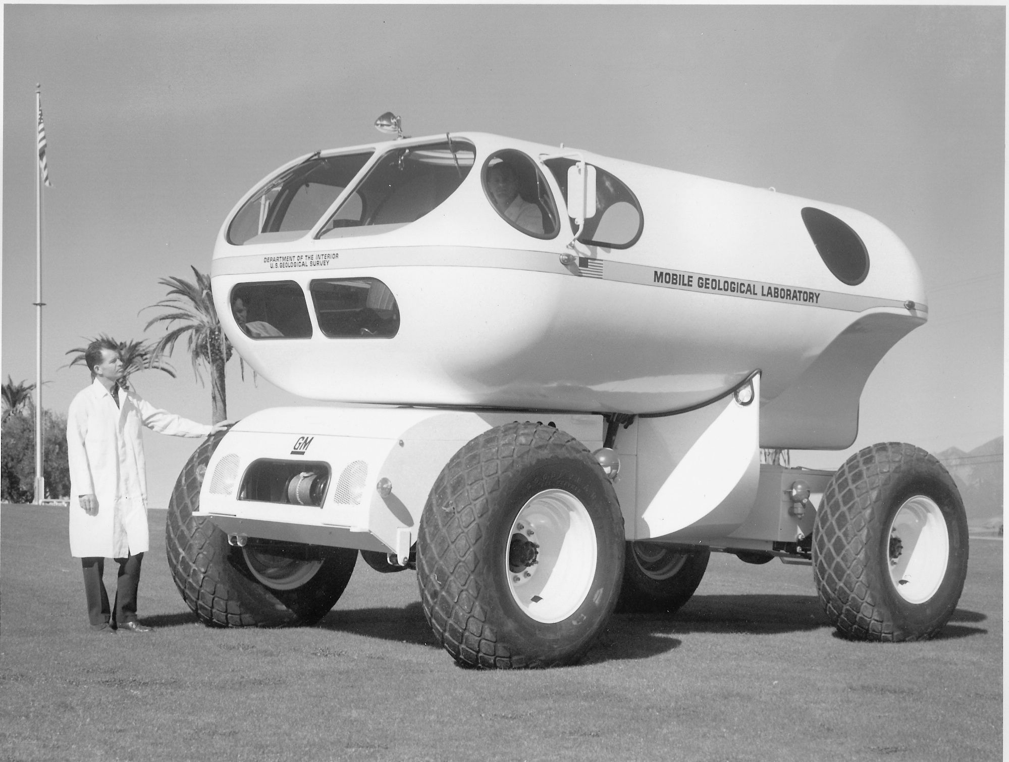
This is a photo of a concept for an earth MOLAB vehicle that was built by General Motors and delivered to the USGS Center of Astrogeology at Flagstaff, Arizona in 1966. It was used in their initial of the Lunar Exploration program. They did a number of human factor research programs with it and it was used in some of the early training of the astronauts in lunar geology simulations. It was returned to MSFC for their use around 1968.
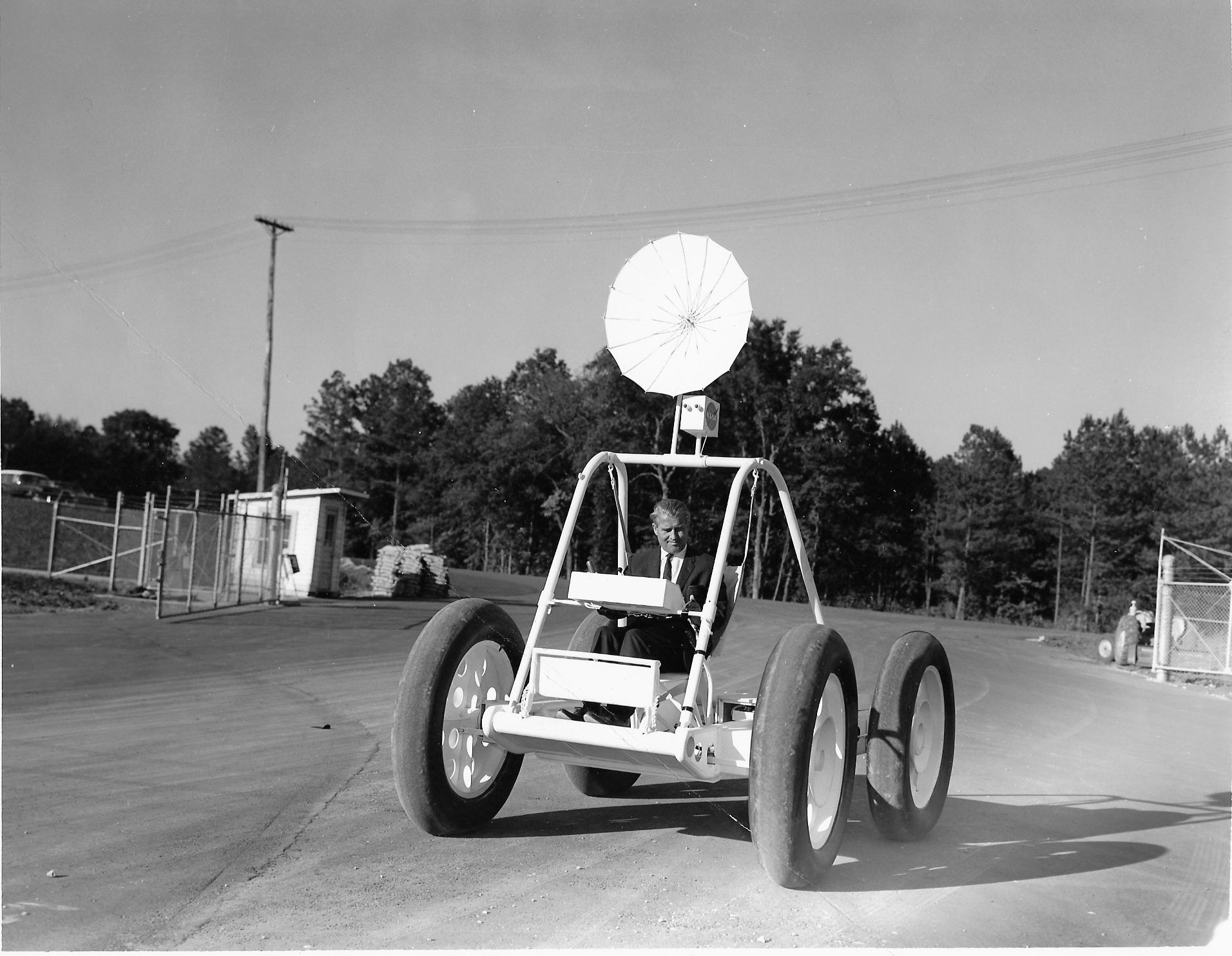
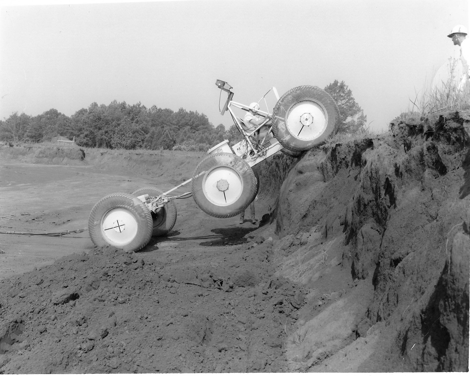
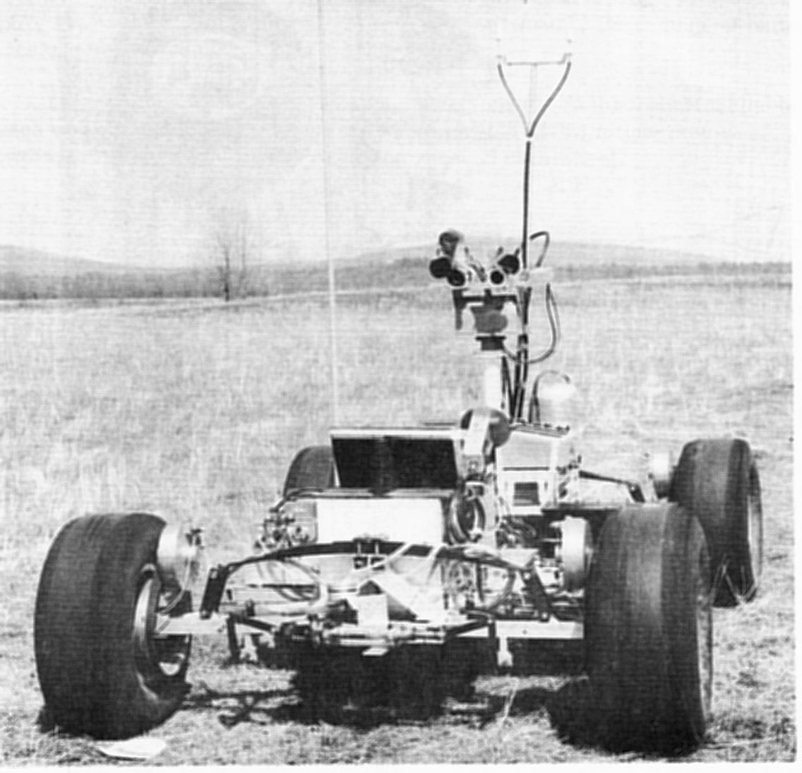
This is a photo of von Braun driving the Brown Engineering small Lunar Rover mobility test article. It was also used for human factors studies and mobility evaluations. This vehicle was developed begining around June 1965 to do an inhouse study of a fixed-geometry, least-risk Local Scientific Survey Module (LSSM) type vehicle to determine it's feasibliity. This vehicle was developed under a subcontract with the Brown Engineering Company here in Huntsville.
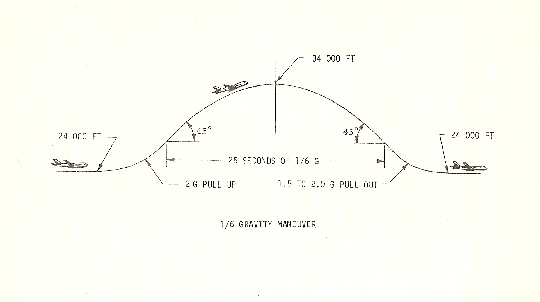
This vehicle was later flown in early 1967 in the USAF KC-135 Low Gravity aircraft while the aircraft was flown to simulate the 1/6 G of the lunar gravity. These flight helped in the redesign of the seats and hand holds with the astronauts climbing into and exiting the vehicle as the flight profiles were being flown. The vehicle was also operated in remote mode to determine the accelerations at both axles, and vehicle center of gravity, vehicle bounce heights as it traveled over simulated obstacles and vehicle speed. Results helped in the design of the hand controller later used in the rover design and in the requirement for an energy absorbing suspension system and a very soft wheel design while driving in the lunar environment. Thes test were conducted under the direction of Richard A. Love, Spacecraft and Payload Systems Branch, Advanced Studies Office, Propulsion and Vehicle Engineering Laboratory of the NASA MSFC.
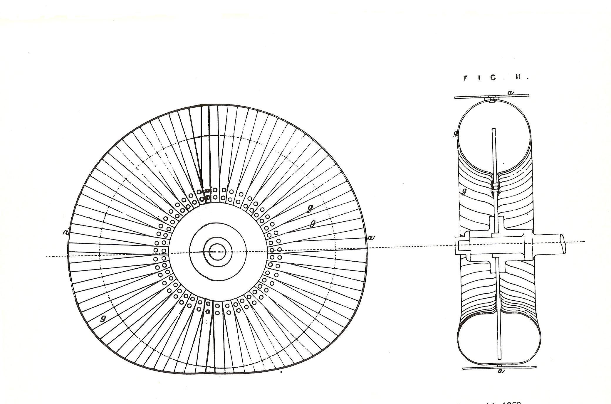
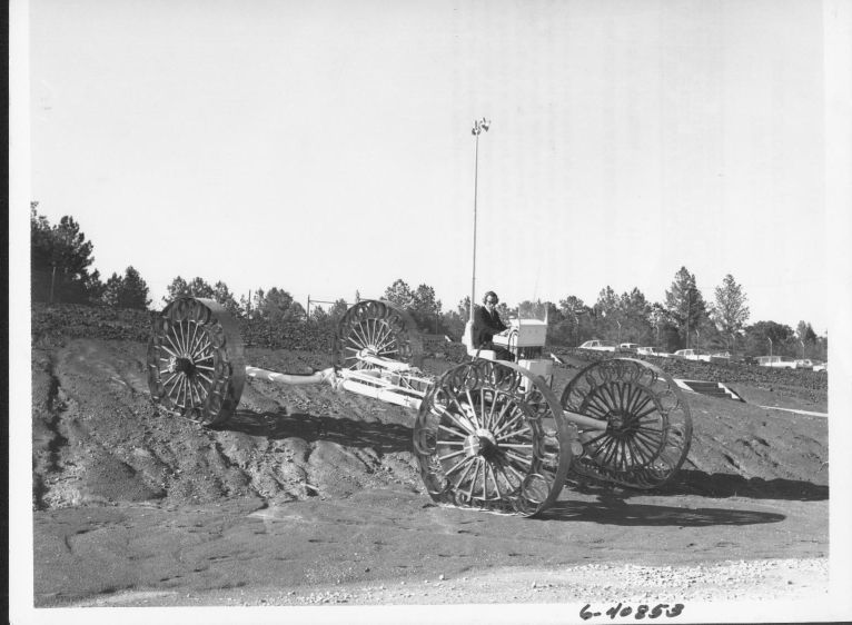
This photo shows a metal wheel concept that was the design of Thomas Kitchens, an englishman, who pattened this design in 1858. Dr. M.G. Bekker often stated that he re- invented the wire mesh lunar rover wheel concept from this design after conducting mobility studies for a small 6 wheeled proposed Surevyor lunar roving vehicle concept that he was developing earlier for the NASA Jet Propulsion Laboratory (JPL).
.
This is a photo of the Bendix Mobility Test Article that were developed for lunar mobility studies of large Lunar Rovers. It was also used for human factors and mobility evaluations here at MSFC.
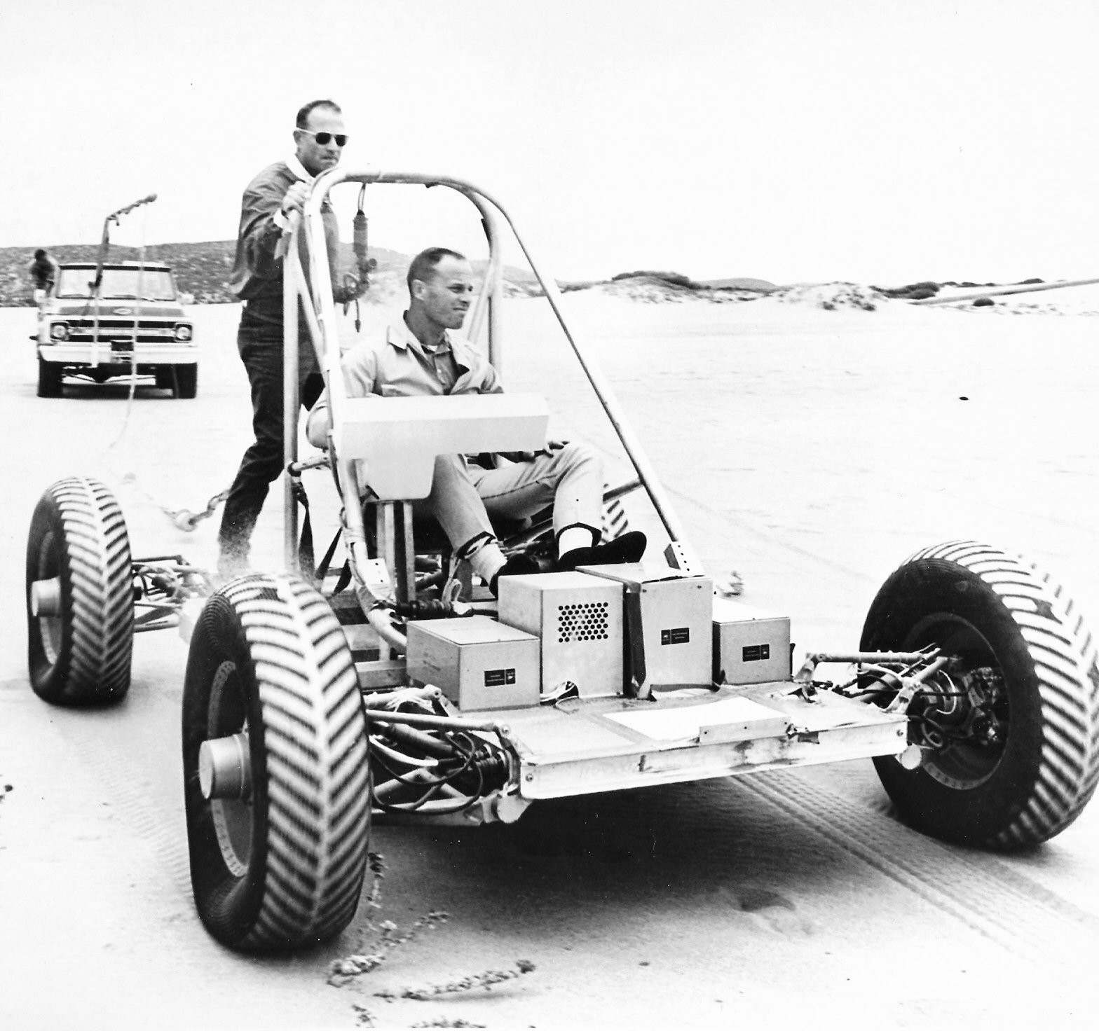
This is a photo of the General Motors concept for a Dual Mode Lunar rover that were developed around 1971 being driven at Pismo Beach, Ca. Astronaut J. Lousma is driving. The truck in the background is providing power for the test. It was used for human factors and mobility evaluations.
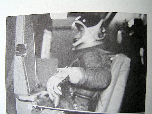
Astronaut John Young in space suit shown driving the MOLAB Simulator. Note the T Handle controller. This T-Handle controller evolved from the astronauts comments while drivin the simulator. The space suit wrist joints created a problem with the movement of the origional hand controlleder so the T-Handle evolved. After MSFC decided to develop the small 2 man unpressurized rover the MOLAG simulator was reconfigured for use in the development of the lunar rover. This simulator an SMK23 airforce flight simulator was modified so that now on the origional moving platform a replica of the LRV driving displays and controls were incorporated.
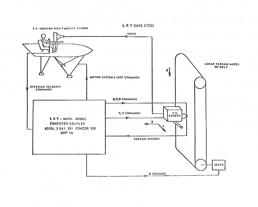
Operations Diagram for the the LRV Simulator..
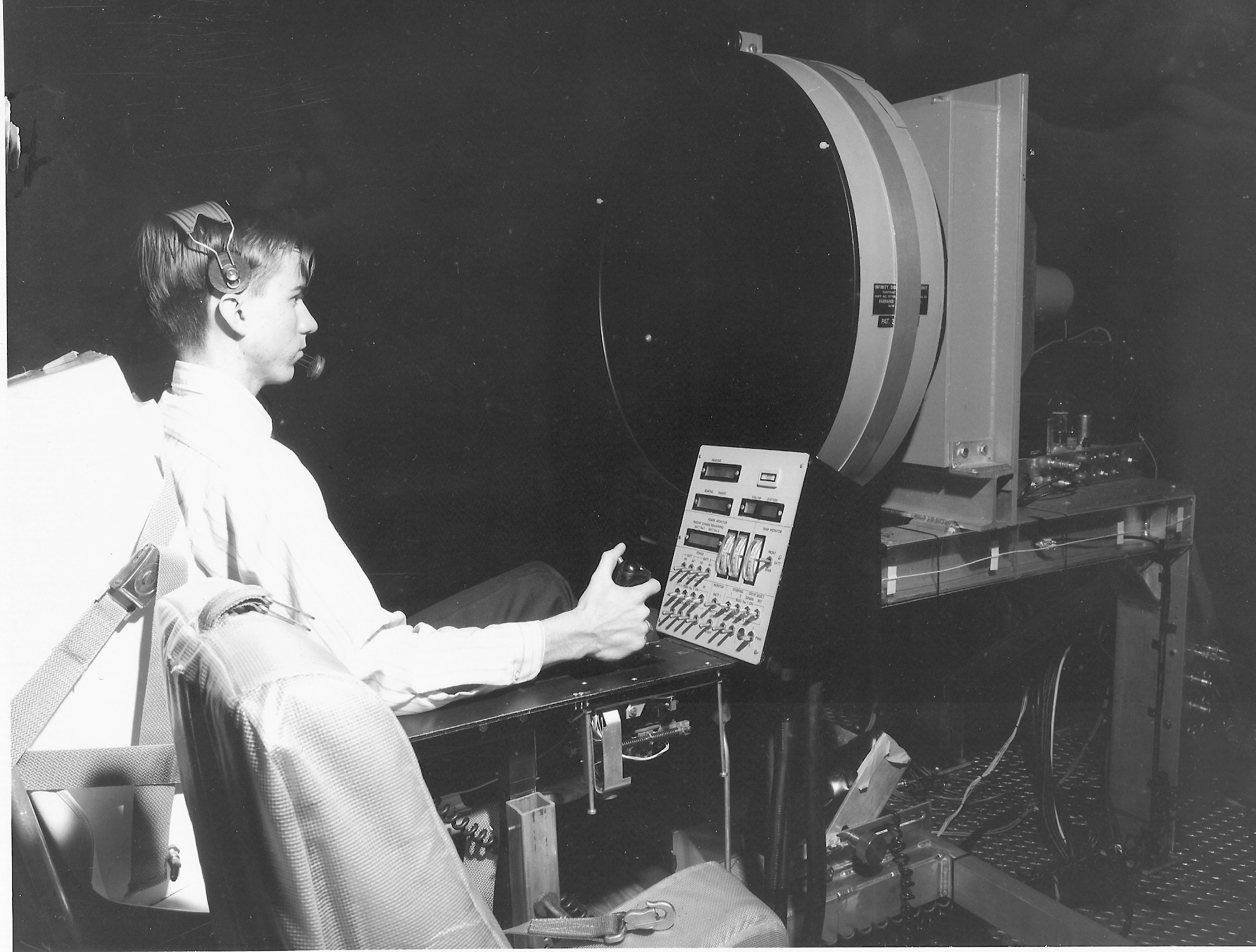
UnSuited Test Subject Driving the LRV Simulator with the large circular TV monitor display.
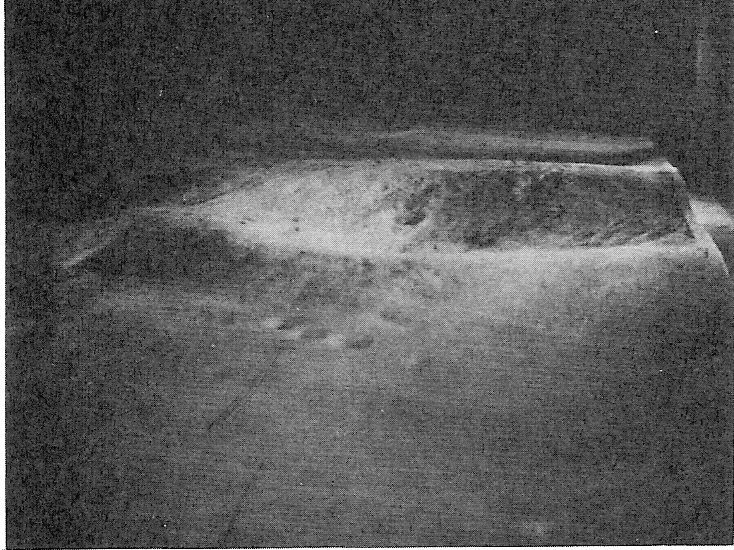
Lunar Crater as seen closeup in the Monitor of the LRV Simulator..
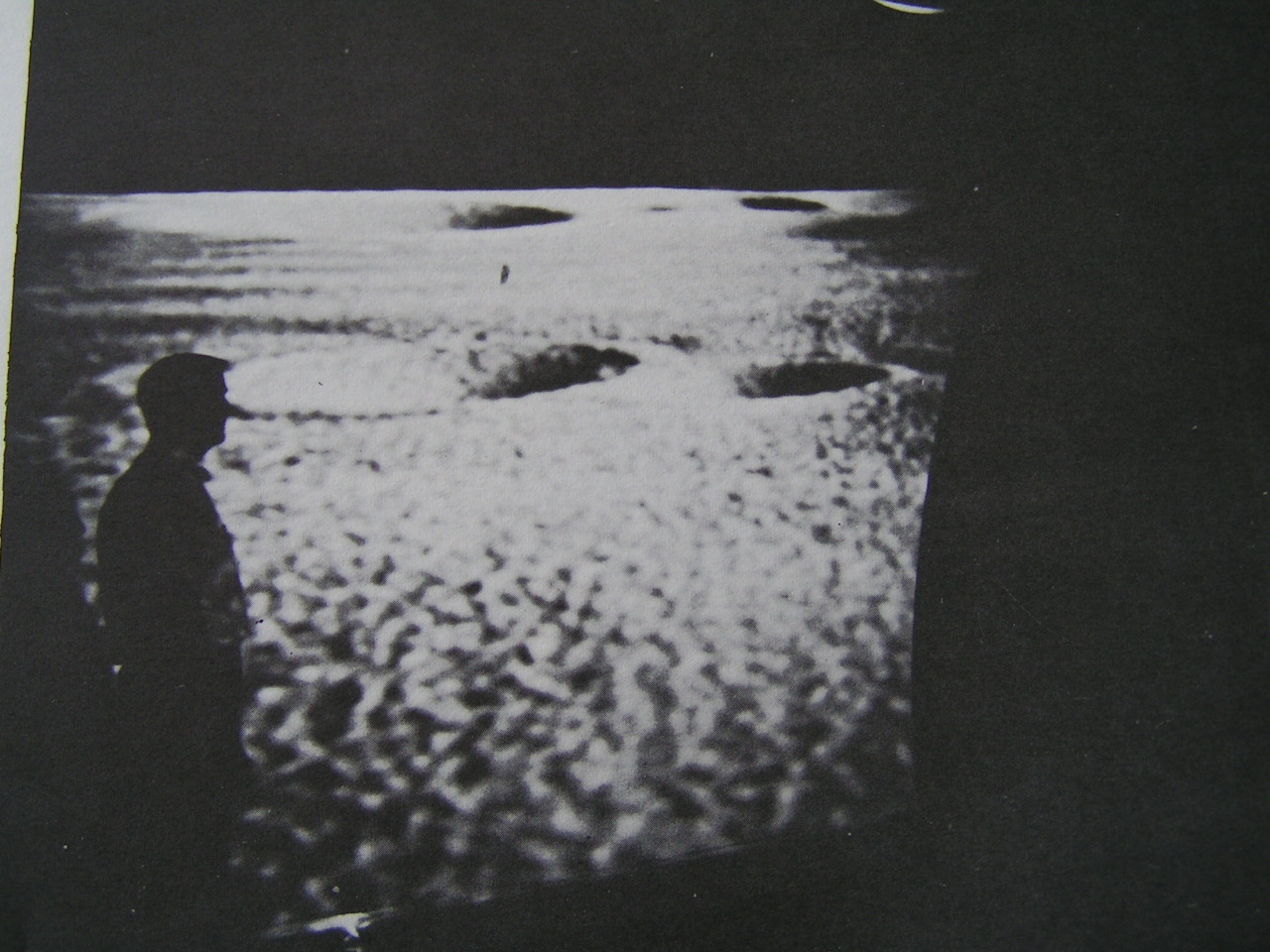
Lunar Surface as seen on the circular TV display.
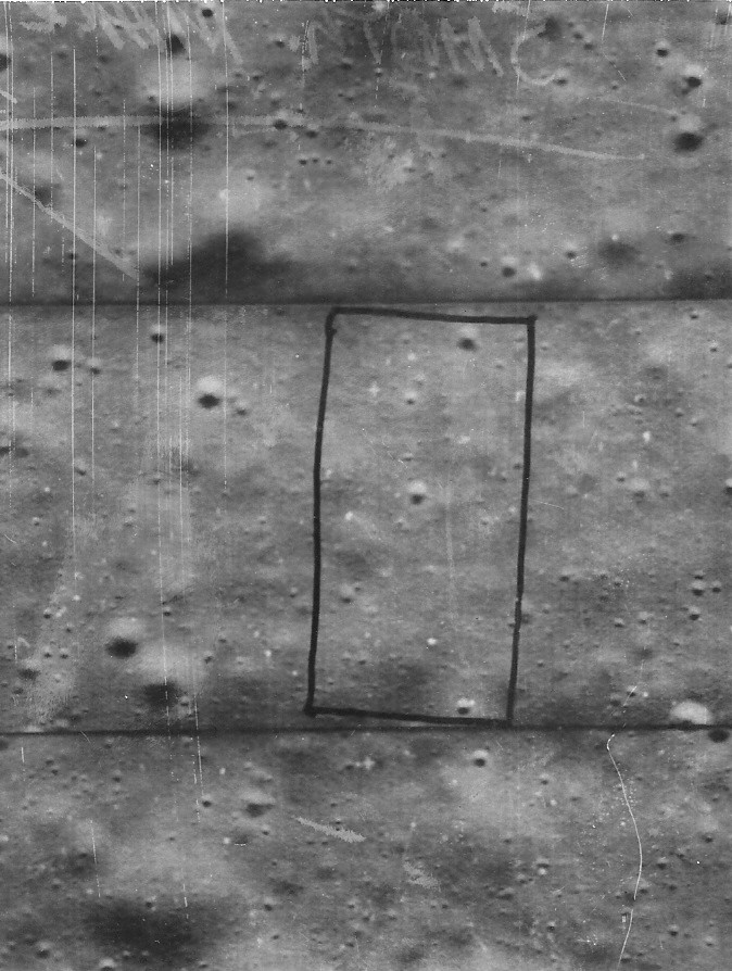
The map used in the simulator was constructed from an Orbiter photo of a smooth Maria area that is shown in black.
The LRV was expected to be operated in the type terrain while on the moon.
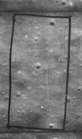
On this photo the area outlined in black shows the actual lunar surface area from which the moving map that was
created for use in the driving simulator.
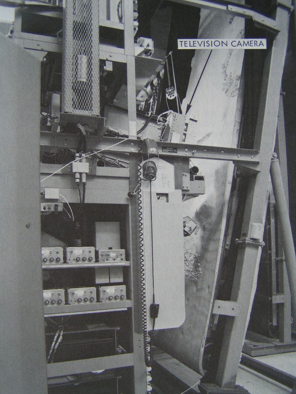
This is a photo of the Moving Map, the simulated vehicle with it's sensors, and small TV camera that was used view the lunar terrain while in the LRV simulator. This was a moving base simulator in which the crew station was a located on a platform that moved in response to the movement of the simulated vehicle motion as it traveled over the moving map while it was being driven by the astronauts. The improved T-Handle controller for the Lunar Rover resulted from the astronauts input the the design reviews that were held after each of their driving scessions in the simulator and driving the MTAs here at the NASA Marshall Space Flight Center's crater field.
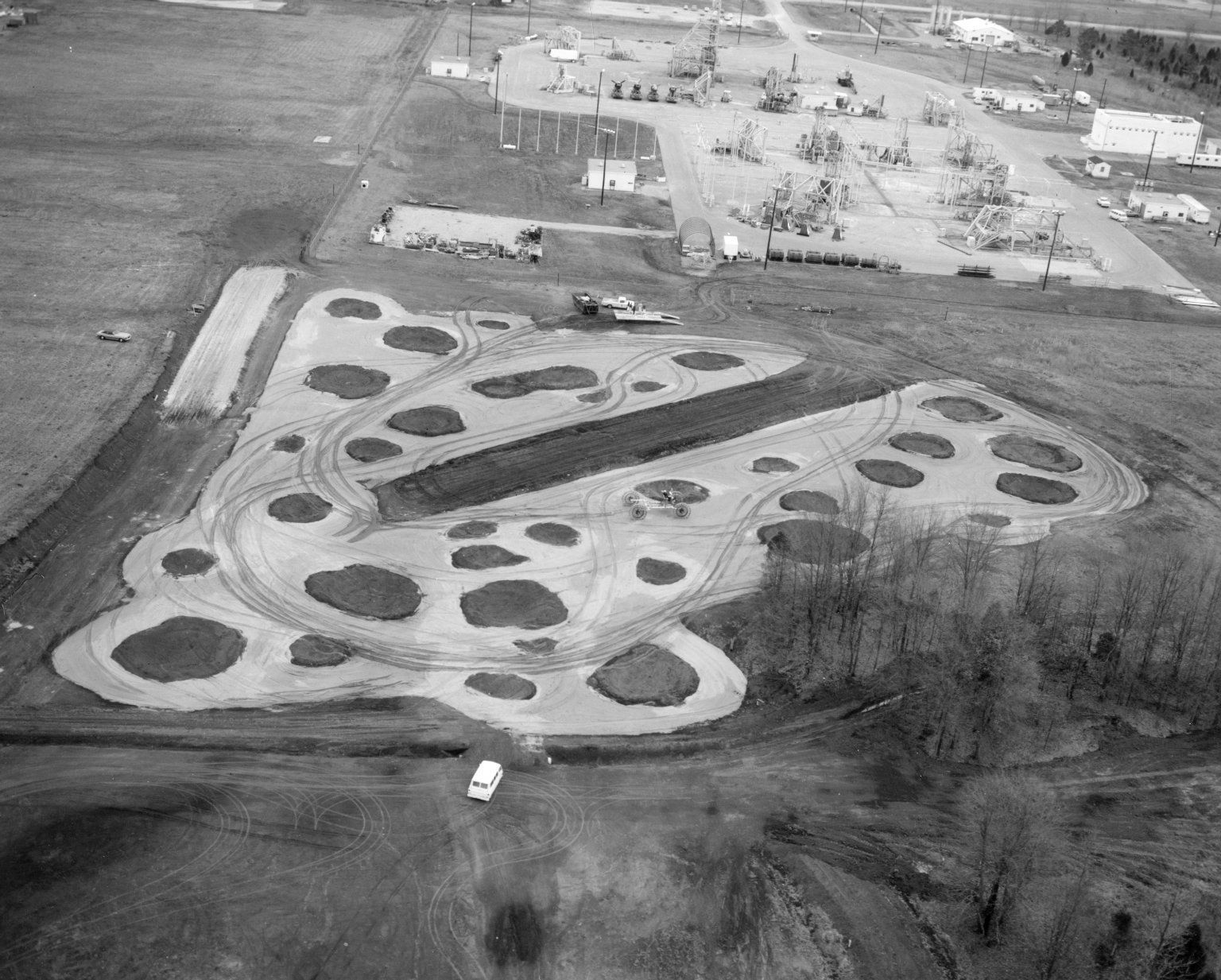
The large MTA Vehicles concepts and the smaller LVR concepts were were tested here at Marshall in our own crater field test
site which was created to represent a typical Luna Mare area and the area around the craters was composed of volcamic cinders to represent the possible type of fine grained material that might be in a smooth mare. There were no simulated ejecta materials around the craters at the test site.
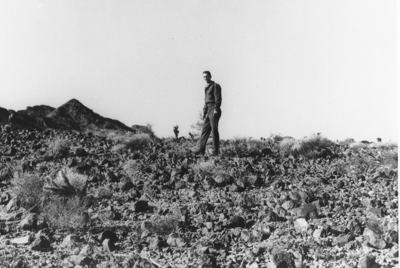
In addition the MTA Vehicles concepts were tested at the US Army's Yuma Proving ground since some areas in the test ranges were considered to be good representation of what the lunar surface might be like in terms of the debris as seen in the Orbiter and Suryevor spacecraft photos of the lunar surface. Some of the test areas were fine grained sandy areas and there were other areas that were littered with various sorts of rocky like debris that simulated the debris thrown out from the craters on the moon.
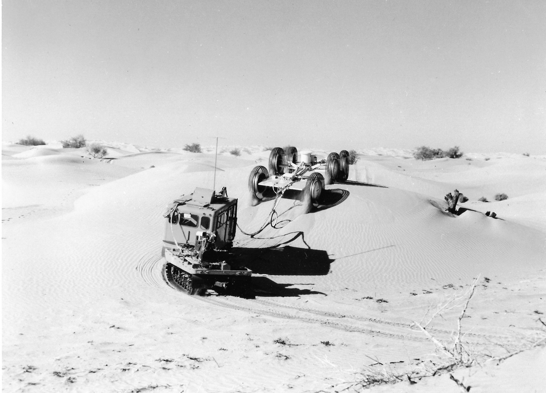
This photo shows some of the Yuma Test Areas that we considered to be representive of the the typical Maria area. with no debris from a nearby small craters. This shows the General Motors vehicle in a mobility test.
This photo shows some of the Yuma Test Areas that we considered to be representive of the the typical Maria area. with some debris from a nearby small crater.
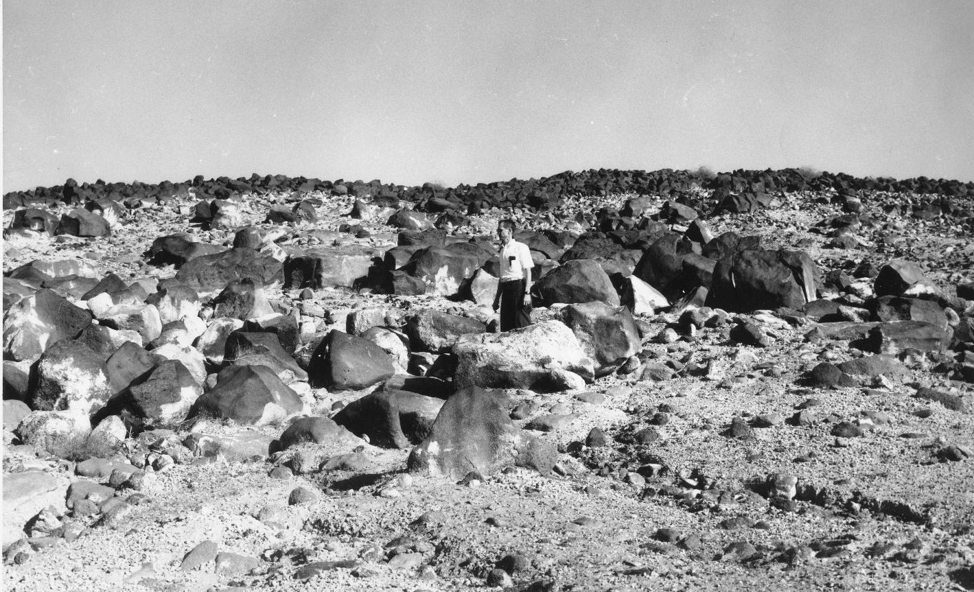
This photo shows some of the Yuma's test areas the represents a large crater with its debris field.
After the LRV was now under contract to be built and delivered after additional Apollo sucessful landings were accomplished, additional studies were continued to develop concepts for a possible Local Scientific Survey Module (LSSM) or dual mode rover. The dual mode rover study contracts began in 1968 and Grumman, Boeing-GM, and Bendix proposed their concepts.This dual mode rover could be used by a two man crew and the after their use it could be operated by remote control from the earth and used to explore interesting geological sites that were out of range of the manned type rover.
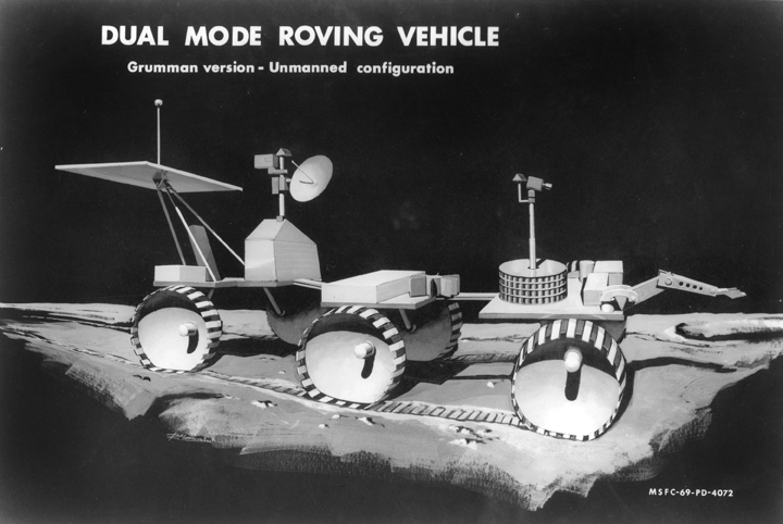
This is an artist concept of the un-manned Grumman Dual Mode Rover.This vehicle concept was never developed after the Lunar Rover was designed and flown.. However Grumman continued their studies by building their small version and did earth mobility tests with it under the direction of Edward Marko.
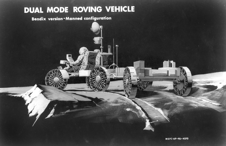
This is an artist concept of the unmanned Bendix Dual Mode Rover. This small vehicle concept was never developed after the Lunar Rover was designed and flown.
This is a photo of the General Motors Dual Mode Test Article climbing over obstacles in a test area.
This vehicle concept was used for their continued mobility studies by General Motors Delco Division
at Santa Barbara, CA.
This is a photo of the MSFC Remote Controlled Dual Mode Test Article.It was equiped with stero cameras and was remotlely controlled from a operation console located in MSFC's Simulation Branch Building.
This vehicle concept was used for their continued mobility studies for the Local Scientific Survey Module (LSSM) inhouse studies.